
ℛ Settings
This tab has multiple sub-tabs, and they are used to provide the user with the ability to maintain the values needed for using the Rose Engine Butler system.
Axis Selection
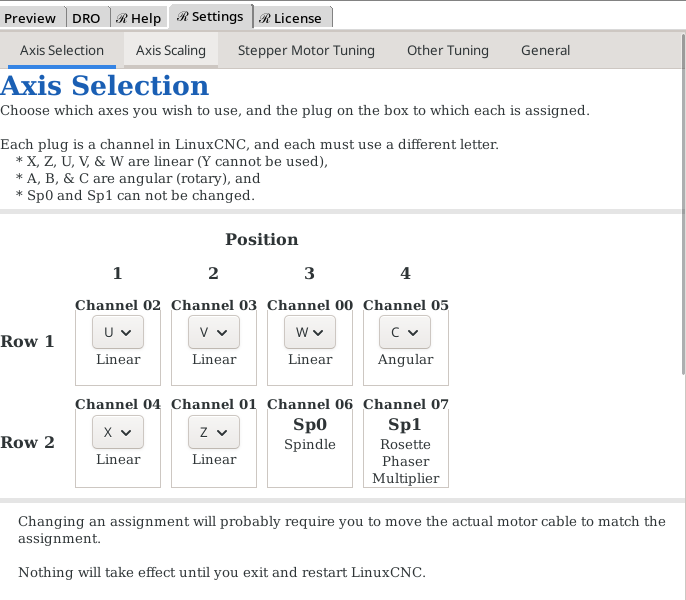
|
|
Reboot Required |
The Rose Engine Butler handles 8 axes:
- Two Spindles
- Main Spindle
- Rosesette Phaser/Multiplier
- 6 configurable axes
On this screen, you select which axes you want to use. You must select from the standardized ① options:
|
Linear Axes |
X & Z (there is no Y axis option in LinuxCNC when configured as a lathe) |
|
U, V, & W (which are parallel to X, Y, & Z, respectively) | |
|
Rotary Axes |
A, B, & C (which are rotations around X, Y, & Z, respectively) |
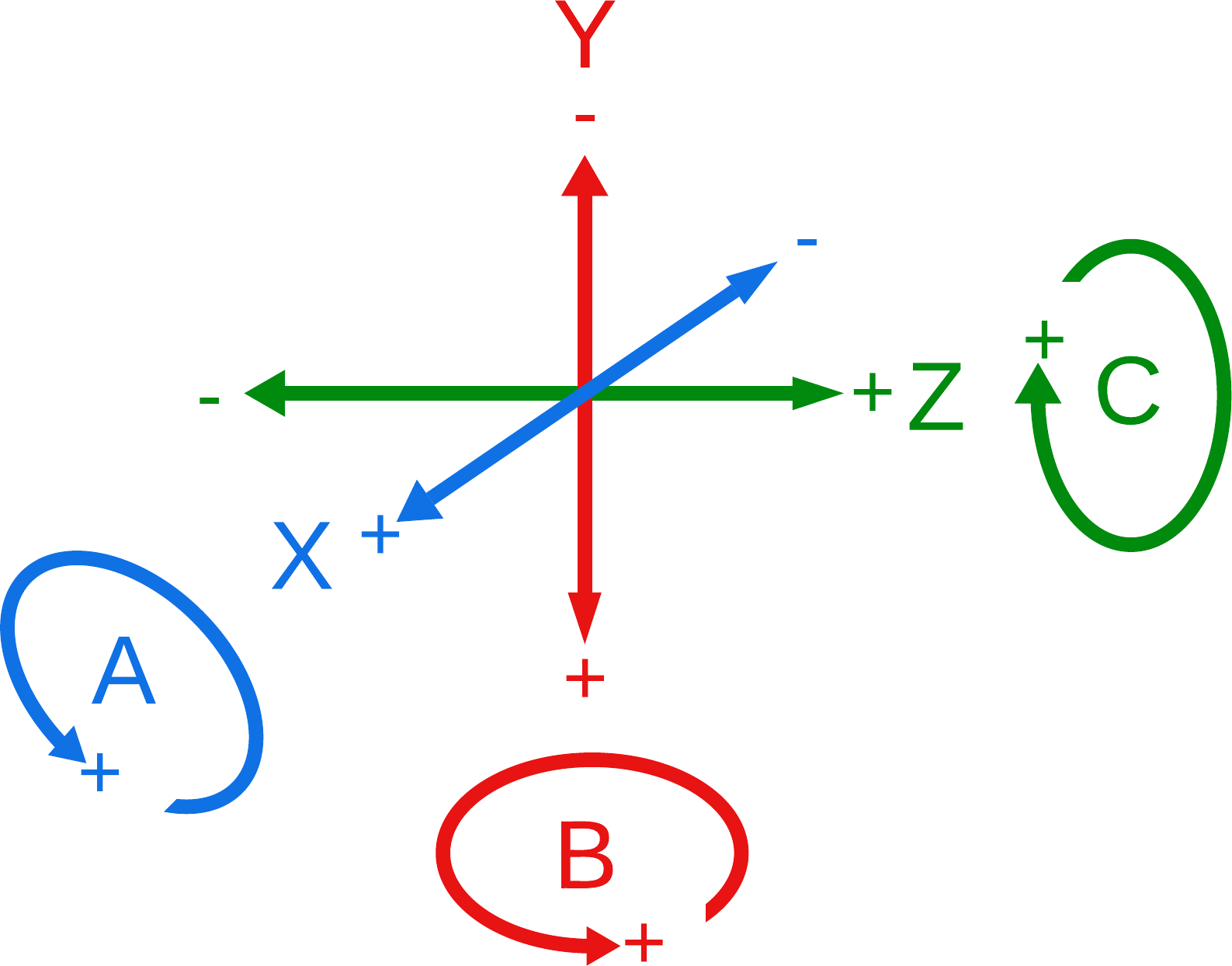
Lathe Axes
Whilst these are the traditional interpretations of those axes, there is nothing particularly critical about them except that some are linear, and others rotary. So, if you need to implement a device which has 3 axes rotating around the spindle axis, you can use A, B, & C to do that -- you'll just have to keep everything straight.
|
|
Additionally, you can select which plugs on the box are used for each axis. The two for the spindles are locked, but the other 6 are configurable.
Impact of Any Changes
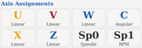
|
Once the changes are made, and the system rebooted, changes made to this screen:
- Set the way LinuxCNC interacts with the plugs on the system (via the channel assignments)
- Update the axes displayed on the right side panel
- Set the options available for the axes on the right side panel (linear axes have different options than angular/rotary axes).
- Update the table displayed at the bottom of the right side panel.
|
|
Notes:
- EIA RS-267-B, AIA NAS-938, & ISO/R 841
|
|
Axis Scaling
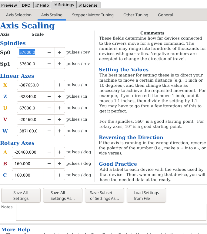
|
Set the desired scale values for the spindles and each axis.
|
Reboot Required |
The comments on the right side of the screen outline some guidance, and best practices, for setting these. There is more, in-depth information at Axis Settings for a Device.
The buttons at the bottom of the screen are:
| Save All Settings |
This is used to make a backup of all the current values you have entered. The data are saved to the default file.
| Save All Settings As... |
This is used to save all the settings to a separate file. The usefulness of this is where you have made a number of changes and want to re-load them later.
| Save Subset of Settings As... |
This is used to save a subset of the system settings. For each axis selected, you will need to select a device name.
| Load Settings from File |
This is used to load the settings saved via one of the 3 options above. If the file is a portion of the settings, only those are loaded (e.g., if you want to load only the settings for a curvilinear slide).
|
|
| User Manual |
Takes you to the page in this user manual which helps you determine the axis settings for a device.
|
|
Notes:
- There are fields for setting the scales for all axes, including the ones not being currently used. The only ones used are for the axes being used.
- This panel is bigger than the screen. To scroll, you will need to use your mouse to move the bar on the right side of this panel. (The Glade system used by LinuxCNC does not accommodate the use of the mouse wheel.)
|
|
Stepper Motor Tuning
|
|
Reboot Required |
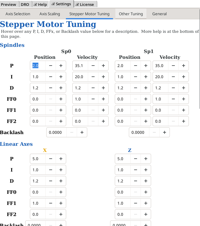
This is used to set the values for each spindle and axis. The tuning already set worked during testing, and the user is cautioned from making significant changes. If you do so, we also recommend you record the starting values (so you can restore them if necessary).
| P | Proportional gain. Too high causes overshoot/oscillation; too low is sluggish. |
| I | Integral gain. Corrects lingering error P alone can't close. Too high causes slow overshoot-then-correct ("windup"). |
| D | Derivative gain. Damps oscillation/overshoot caused by P and I. |
| FF0 | Zeroth order Feedforward gain. Normally left at 0 for a position loop. |
| FF1 | First order Feedforward gain. Lets the loop anticipate motion instead of only reacting to error. On this machine, FF1 - not P/I - does most of the tracking. |
| FF2 | Second order Feedforward gain. Can compensate for inertia. |
| Backlash | Backlash compensation. Distance the mechanism can move, after reversing direction, before mechanical slack (leadscrew/gear play) is taken up and real motion resumes. Set to the measured lost motion for this axis; 0 disables compensation. |
For the spindles (Sp0 & Sp1), there are both position and velocity values.
- The position values are used when indexing the spindles using the Indexing buttons or the M19 gcode.
- The velocity values are used when running the spindles via the Run Operation buttons, or when using M3 or M4 gcodes.
|
|
Notes:
- There are fields for setting the scales for all axes, including the ones not being currently used. The only ones used are for the axes being used.
- More information is available at:
- These get saved when the program is exited, or when one of the Save Settings buttons is used on the Axis Scaling tab.
- This panel is bigger than the screen. To scroll, you will need to use your mouse to move the bar on the right side of this panel. (The Glade system used by LinuxCNC does not accommodate the use of the mouse wheel.)
|
|
Other Tuning
|
|
Reboot Required |
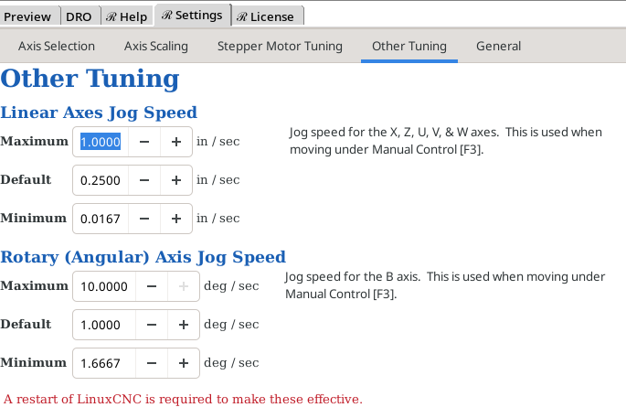
Use this to set the maximum, default, and minimum jogging speeds for
- Linear axes: Jog speed for the X, Z, U, V, & W axes.
- Rotary (Angular) axis: Jog speed for the A, B, & C axes.
These are used when moving under Manual Control [F3].
|
|
General
|
|
Reboot Required |
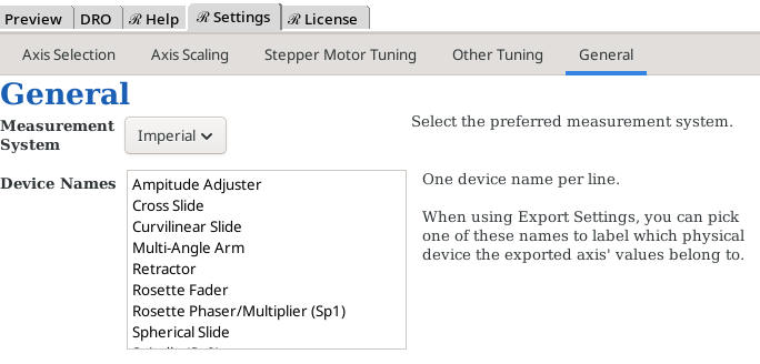
There are some general values which get set here:
- The measurement system to be used (Imperial or Metric)
- Device names to be used for the selection fields. You enter them as one device name per line.
| spacer line |
|
eMail comments to |