
Indexing
Axes Colors
| Color | Axis | Movement Control | |||||
| Neg | Pos | Neg | Pos | ||||
| Yellow | X | U | A | 
| 
| 
| 
|
| Red | V | B | 
| 
| 
| 
| |
| Blue | Z | W | C | 
| 
| 
| 
|
| Black | Spindles (Sp0 & Sp1) | 
| 
| ||||
On this page, the axis letters are colored to assist the user. (Note: LinuxCNC does not allow for a Y axis when running as a lathe.)
Every axis has a row of controls on the user screens, but only the axes selected for use can be operated - the others are grayed out. For example, in the screen shown below, the user has selected to use the X, Z, U, V, W, and C axes, so the A and B rows are grayed out.
The table at the bottom of the user screen titled, Axis Assignments, shows the current axis assignments. It is updated the next time Rose Engine Butler is started after the selected axes are changed.
|
|
Indexing Tab
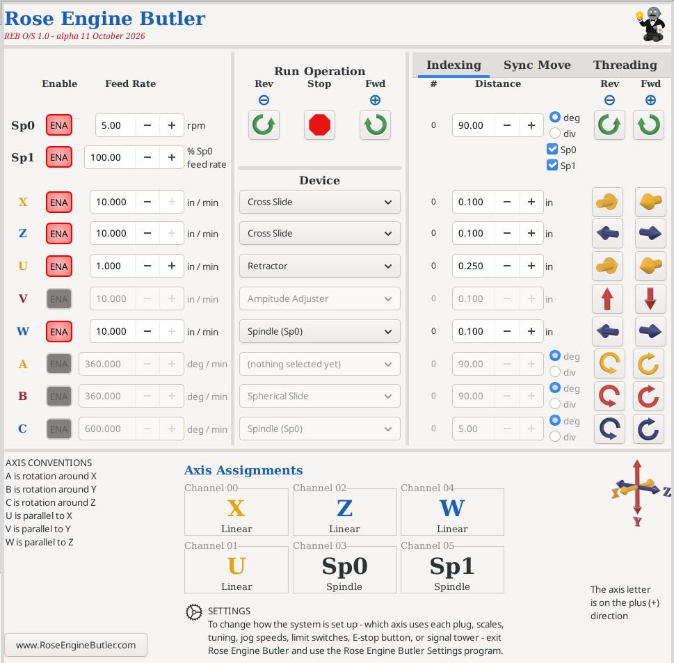
The Indexing tab is used to drive motors on the selected axis, one at a time.
The buttons to the right initiate the indexing operation in either the reverse (- movement) or forward (+ movement) direction.
Images on the buttons show the movement direction.
Counter
There is a counter for the number of indexing operations which have been performed. This count is shown as the number to the left of the indexing Distance.
- It is incremented by 1 for each Fwd indexing operation.
- It is decremented by 1 for each Rev indexing operation.
- The count starts at 0 when Rose Engine Butler is started. (It is not saved when you exit and then re-start Rose Engine Butler.)
- If the indexing Distance is changed, it reverts to 0. (The assumption is that you are starting a different activity.)
- You can set it back to 0 yourself by double-clicking on the number (double-clicking is implemented so you do not accidentally reset it).
Spindles
For the spindles, this can be in either degrees or divisions of a circle.
Additionally, you can choose to index:
- the main spindle (Sp0),
- the rosette phaser multiplier (Sp1), or
- both
If neither is selected, nothing happens.
Linear Axes
For linear axes, this is a distance. The UOM shown for these axes, and used by the system, is based on the Measurement System selection.
Angular (Rotary) Axes
For the angular axes (A, B, and C), this is a rotary indexing, in degrees or divisions of a circle.
| spacer line |
|
eMail comments to |