
Main Screen
Axes Colors
| Color | Axis | Movement Control | |||||
| Neg | Pos | Neg | Pos | ||||
| Yellow | X | U | A | 
| 
| 
| 
|
| Red | V | B | 
| 
| 
| 
| |
| Blue | Z | W | C | 
| 
| 
| 
|
| Black | Spindles (Sp0 & Sp1) | 
| 
| ||||
On this page, the axis letters are colored to assist the user. (Note: LinuxCNC does not allow for a Y axis when running as a lathe.)
Every axis has a row of controls on the user screens, but only the axes selected for use can be operated - the others are grayed out. For example, in the screen shown below, the user has selected to use the X, Z, U, V, W, and C axes, so the A and B rows are grayed out.
The table at the bottom of the user screen titled, Axis Assignments, shows the current axis assignments. It is updated the next time Rose Engine Butler is started after the selected axes are changed.
|
|
At Startup
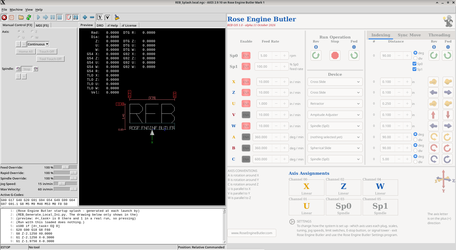 System at startup (Base Box) |
When the Rose Engine Butler system is started, the screen above will be displayed.
At this point, the LinuxCNC system is still in an "Estop" and "off" state.
After
- releasing the Estop (F1), and
- powering the system on (F2),
the same screen will no longer be grayed out, and will be as shown below.
Note: This state can be also encountered if an error is encountered.
|
|
After Startup
After
- releasing the Estop (F1), and
- powering the system on (F2),
the screen below will be shown.
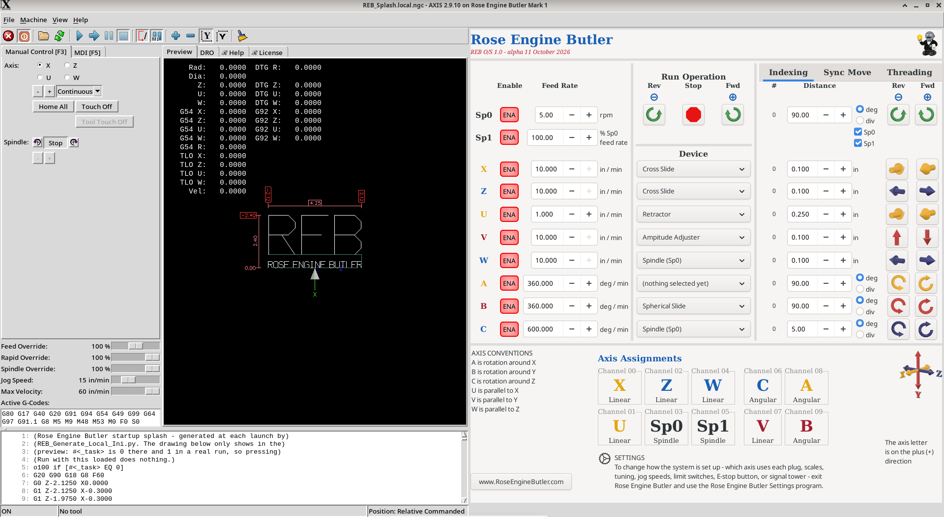 System after startup (Base Box with Expansion Box) |
For the panel on the right side of the screen, all the axes which Rose Engine Butler supports are shown. The axes which are not assigned to a channel using the Rose Engine Butler Settings are grayed out.
The controls on this panel to the right are:
| ENA |
Used to enable or disable an axis.
|
| Feed Rate |
Used to set the feed rate (speed) for movements on this page. The unit of measure (UOM) for that speed is shown on the screen. These feed rates are not used on the Manual Control / Jogging (F3) nor the MDI Tab (F5). The UOM shown, and used by the system, is based on the Measurement System selection. |
| Run Operation |
Used for running the spindles. Notes for the Sp1 spindle (rosette phaser/multiplier)
|
| Device |
This allows the user to denote the use of the non-spindle axes. The values shown are in the Device Names list on Settings - Other. |
| spacer line |
|
eMail comments to |